Engineering & personal work

Projects

Hardware, robotics and the decisions behind them.

Engineering project

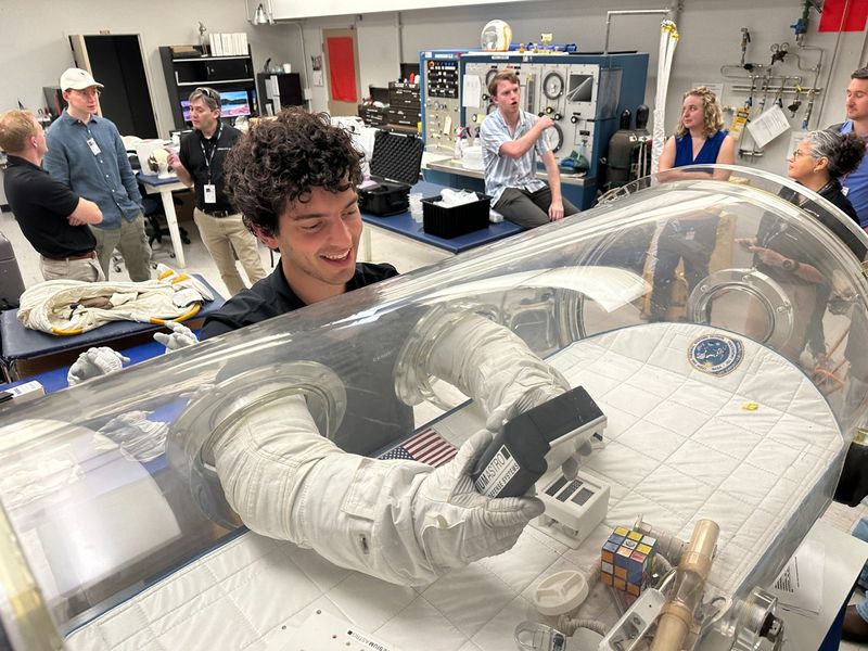
Lunar navigation device

A glove-operable prototype built at CesiumAstro, with a capstone engineering model underway.

Explore project →
Engineering project

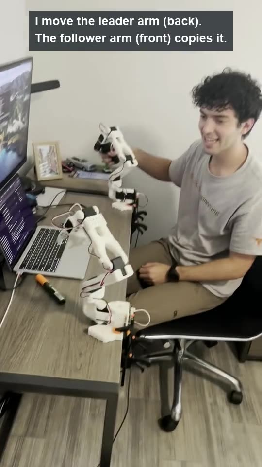
SO-101 robot arms

A leader–follower platform for recording demonstrations and studying objective inference.

Explore project →
Schematic of a mixed traffic corridor Two lanes of vehicles travelling left to right. Connected vehicles are filled; human-driven vehicles are outlines. Dotted arcs suggest local information sharing between nearby connected vehicles. No parameters or results are encoded.
Illustrative schematic

Engineering project

Connected-vehicle traffic

A microsimulation for studying local coordination among connected and human-driven vehicles.

Explore project →

More projects

Course project · Fall 2025

3D-printed dragonfly wing

At the University of Edinburgh, I owned the biomimetic structural design of a 250 mm wing that measured about 85:1 base-to-tip stiffness in point-load tests, against roughly 100:1 for Aeshna dragonflies. It was not flight-tested.
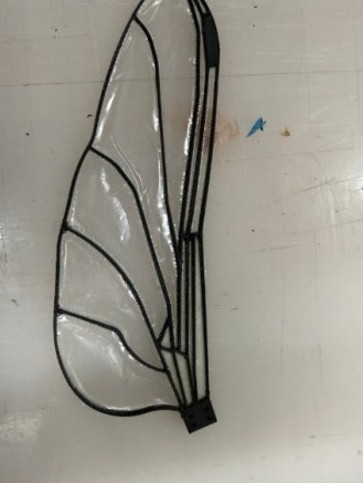
3D-printed dragonfly wing prototype: black vein structure with a clear TPU membrane.
Test data and design
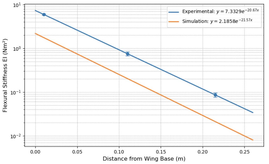
Log-scale plot of flexural stiffness EI against distance from the wing base, 0 to 0.25 m. Experimental points at three stations with error bars follow an exponential fit falling from about 7.3 to under 0.1 N·m²; the simulation line runs parallel but lower.
Measured and simulated stiffness along the span (team report, Fig. 8). The printed wing came out stiffer than the FEA predicted, which the team put down to material changes during printing.
Result
EI of 7.33 ± 0.25 N·m² at the base and 0.086 ± 0.01 N·m² at the tip. FEA predicted about 105:1.
Test
Point loads on an Instron 3369 at fixed spans, 20 mm/min, repeated runs. EI from deflection, treating the wing as a uniform cantilever.
Geometry
The five main longitudinal veins and their supporting veins from published morphology; small cross-veins dropped.
Root stiffness
The natural root corrugation was too fine to print, so we simulated and tested two substitutes: a thickness gradient, and continuous carbon fibre through the veins nearest the root.
Materials
Onyx (chopped-carbon nylon) veins, close to biological veins in specific stiffness; 0.03 mm TPU membrane, which resists cracking when flexed.
Limits
About 8.6 times stiffer than a scaled biological estimate, set by the minimum printable thickness.
FEA design iterations, 0.1 N tip load
IterationVeinsBase:tip EI
1PLA, 1.5 mm2.0
2Onyx, 1.5 mm38.4
3Onyx + CF, 1 mm65.2
4 (built)Onyx + CF, 1.5 mm104.9
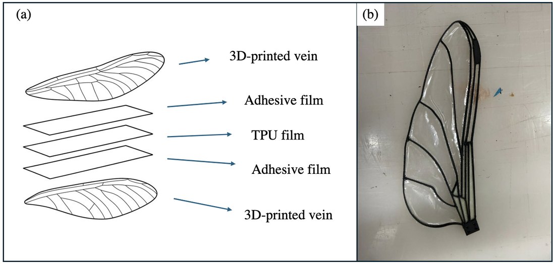
Left: exploded diagram of a five-layer layup, 3D-printed vein, adhesive film, TPU film, adhesive film, 3D-printed vein. Right: photo of the finished wing.
Five-layer layup (team report, Fig. 4). We switched to it after printing Onyx onto the TPU film melted the film.

Modal analysis put the first bending mode at 12.1 Hz and the first torsional mode at 26.0 Hz, around a 20 Hz flapping target for a ~100 g micro air vehicle.

I also contributed to the analysis.

Team: Bruce You, Han Chen, Koby Szeszko, Wenxuan Ma and me; supervised by Dongmin Yang. Source: team report, “Iterative Design and Analysis of 3D-Printed Biomimetic Dragonfly Wings,” University of Edinburgh, 2025.

Personal · in progress

Equatorial telescope mount

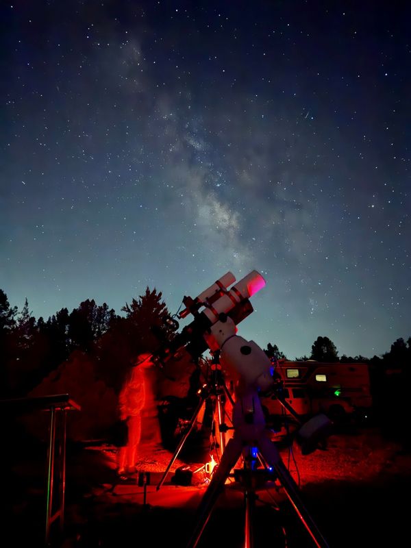
A tracking mount with a 100:1 harmonic gearbox and a 3:1 belt stage, 300:1 overall. I designed the housing and belt tensioning and ran the telescope-load calculations. Motor control and tracking come next.

Personal build

Robotic hand

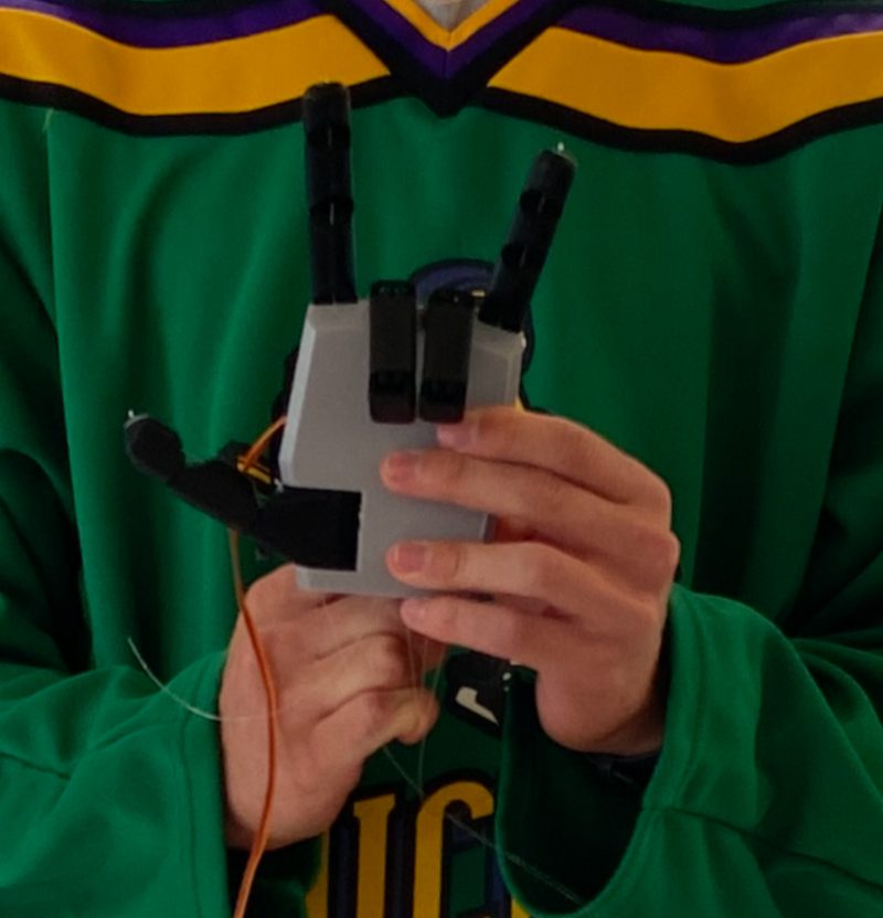
A fully 3D-printed hand modeled in Onshape from my own hand’s dimensions. Servos in the forearm run on C++, and Python/OpenCV hand tracking lets it mirror my movements.
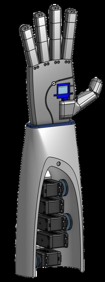
CAD render of the robotic hand with an open palm, on a forearm with a cutaway showing a column of servos.
Photos
CAD render of the robotic hand and forearm; the forearm cutaway shows the servos stacked inside.
Onshape model.
The printed robotic hand held in two hands, with wiring trailing from the base.
The printed hand.

Personal build

Variable-depth hangboard

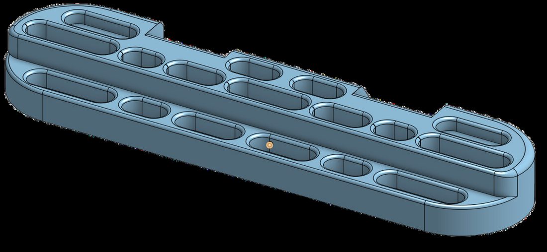
A cheaper climbing hangboard with holds of several depths, modeled in Onshape and routed from wood with Fusion 360 CAM toolpaths.
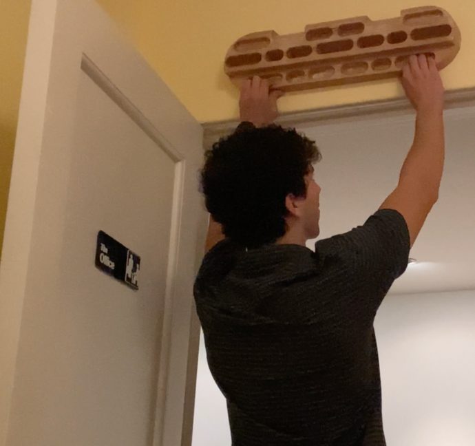
Seth hanging from a wooden climbing hangboard mounted above a doorway.
CAD
Onshape model of the hangboard: a long board with two rows of rounded slots cut to form holds.
Onshape model.

Personal builds

Lightsabers V2 and V1

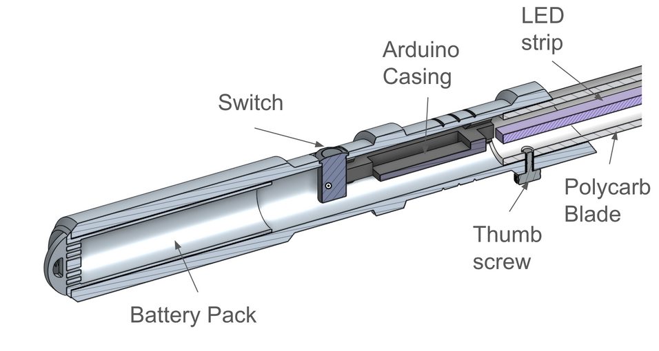
V2 is my own design, with an Arduino, an 18650 battery and an addressable RGB LED strip. V1 was a film-hilt replica designed to be made on a lathe, mill and 3D printer.
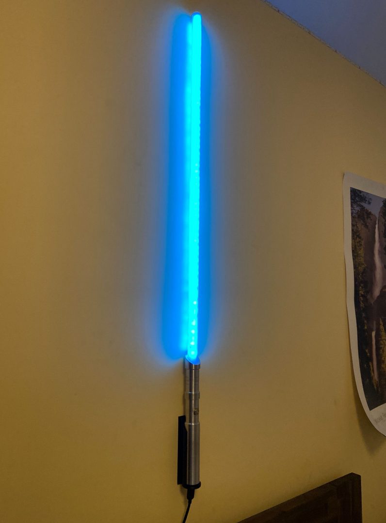
Lightsaber V2 mounted on a wall with its blue polycarbonate blade lit.
Internals and V1
Cutaway CAD of the V2 hilt with labels: battery pack in the lower hilt, a switch, the Arduino casing, a thumb screw, the LED strip and the polycarbonate blade.
V2 cutaway: battery pack, switch, Arduino casing, thumb screw, LED strip and polycarbonate blade.
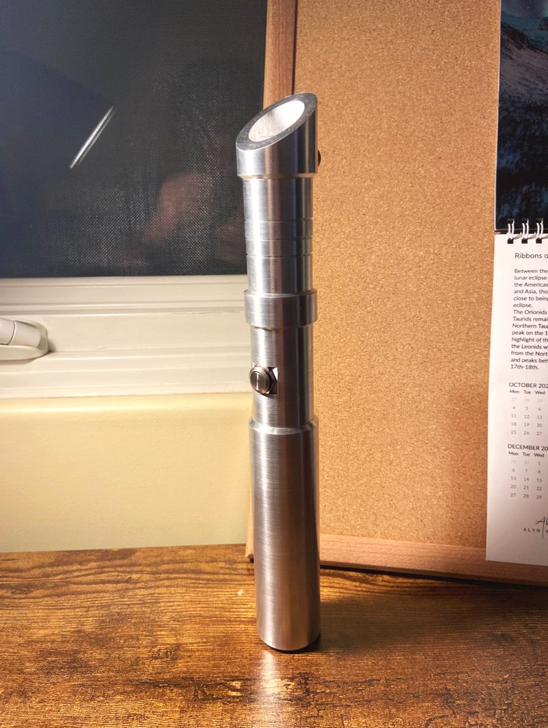
The finished V2 aluminum hilt standing on a wooden desk.
V2 hilt.
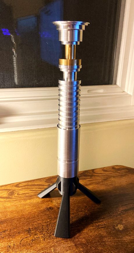
The machined V1 replica hilt standing upright on a three-legged stand.
V1. I redesigned the bottom piece as a desk stand.
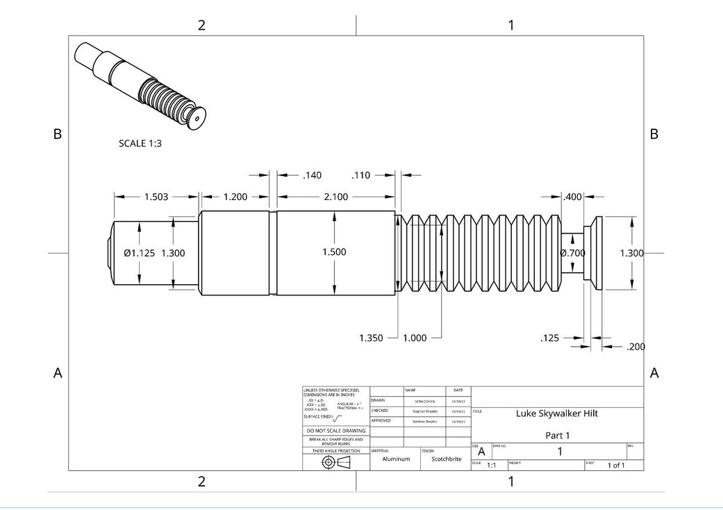
Dimensioned engineering drawing of the V1 hilt part, titled Luke Skywalker Hilt, with diameters and lengths in inches.
V1 part drawing.
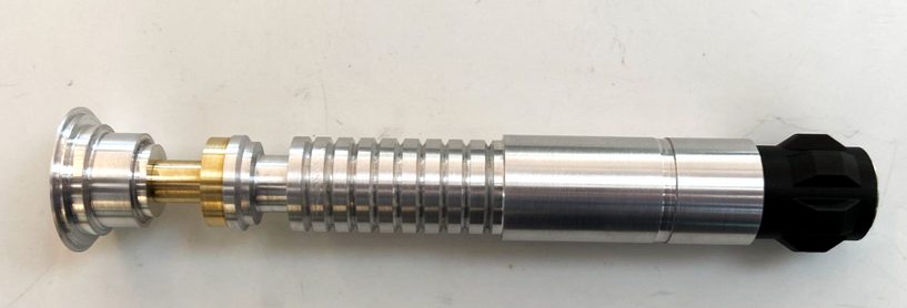
The machined V1 hilt lying on its side: polished aluminum with ribbed grip, brass ring and black end cap.
V1 as made.

Award · December 2021

Onshape speed-modeling challenge

First place among 1,749 attempts, modeling a flexible shaft coupling in 2 min 44 s. Watch on YouTube
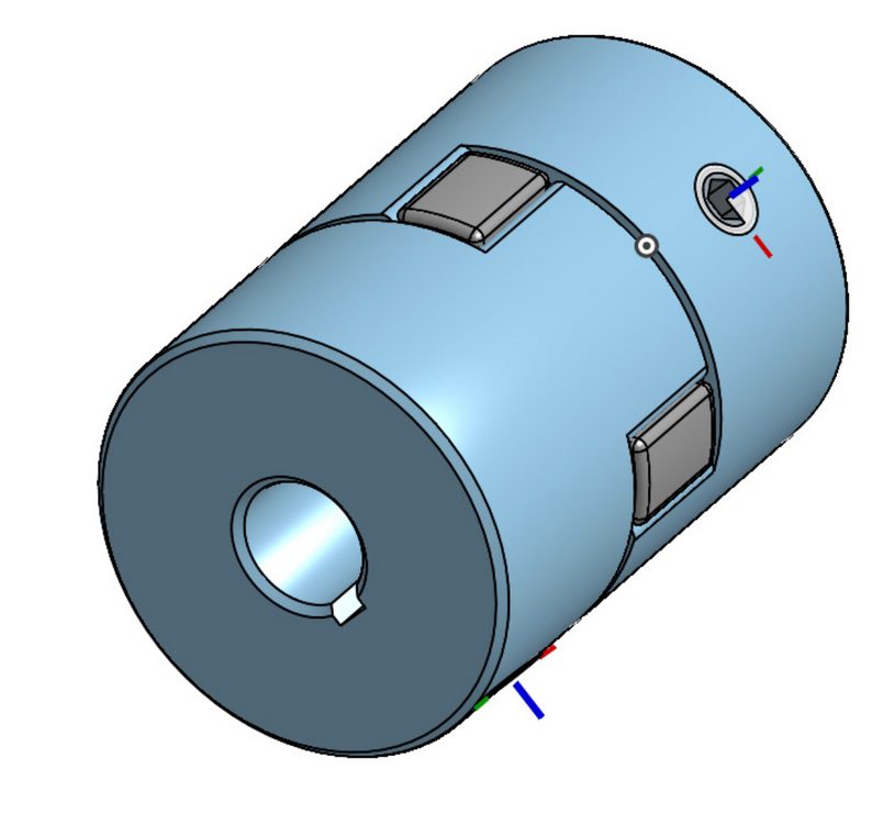
Onshape CAD model of a light-blue flexible jaw coupling with grey inserts.

Personal build · high school graduation

LED-matrix graduation cap

An Adafruit Feather runs C++ designs I wrote on an LED matrix, changing every 30 seconds.
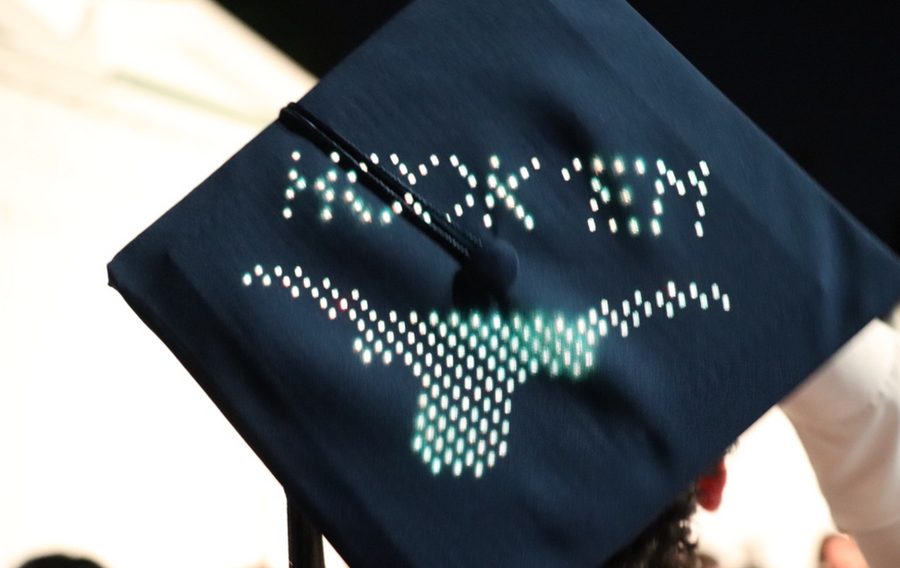
A graduation cap with an LED matrix displaying “Hook ’em” and a Longhorn.